Standby and takeover configurations
There are two basic types of cluster configuration:
- Standby
- This is the traditional redundant hardware configuration. One or more standby nodes are set aside idling, waiting for a primary server in the cluster to fail. This is also known as hot standby. From now on, we refer to an active/passive configuration to mean a two-node cluster with a hot standby configuration.
- Takeover
- In this configuration, all cluster nodes process part of the cluster's workload. No nodes are set aside as standby nodes. When a primary node fails, one of the other nodes assumes the workload of the failed node in addition to its existing primary workload. This is also known as mutual takeover.
Typically, implementations of both configurations will involve shared resources. Disks or mass storage such as a Storage Area Network (SAN) are most frequently configured as a shared resource.
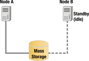
As shown in Figure 1, Node A is the primary node, and Node B is the standby node currently idling. Although Node B has a connection to the shared mass storage resource, it is not active during normal operation.

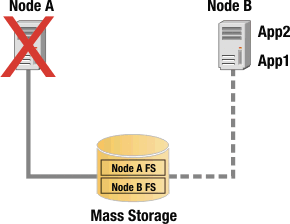
After Node A fail over to Node B, the connection to the mass storage resource from Node B will be activated, and because Node A is unavailable, its connection to the mass storage resource is inactive. This is shown in Figure 2.

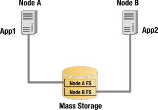
By contrast, in the following a takeover configuration, both Node A and Node B access the shared disk resource simultaneously. For HCL Workload Automation high-availability configurations, this usually means that the shared disk resource has separate, logical file system volumes, each accessed by a different node. This is illustrated in Figure 3.

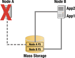
During normal operation of this two-node highly available cluster in a takeover configuration, the filesystem Node A FS is accessed by App 1 on Node A, and the filesystem Node B FS is accessed by App 2 on Node B. If either node fails, the other node takes on the workload of the failed node. For example, if Node A fails, App 1 is restarted on Node B, and Node B opens a connection to filesystem Node A FS. This is illustrated in Figure 4.

Takeover configurations are more efficient than standby configurations with hardware resources because there are no idle nodes. Performance can degrade after a node failure, however, because the overall load on the remaining nodes increases.